UNI EN ISO 16090-1 Sicurezza Centri di lavoro, fresatrici, macchine transfer / Taglio a freddo metalli - P.1 Suddivisione in gruppi
ID 17927 | Rev. 1.0 del 20.06.2023 / Documento in allegato
La UNI EN ISO 16090-1:2023 (tipo C ai sensi della EN ISO 12100:2010), specifica i requisiti tecnici di sicurezza e le misure di protezione per la progettazione, la costruzione e la fornitura delle macchine utensili utilizzate per il taglio a freddo di metalli e materiali non combustibili (alesatrici, fresatrici, centri di lavoro, macchine transfer e macchine speciali.
La norma non è armonizzata per la Direttiva macchine 2006/42/CE.
La UNI EN ISO 16090-1:2023 sostituisce la UNI EN ISO 16090-1:2019. Le principali novità della nuova edizione sono:
- introduzione nuove funzioni di sicurezza (Allegato J);
- modifica della MSO (modalità di funzionamento sicuro) in MO (modalità di funzionamento);
- introduzione obbligo uso di un comando di abilitazione nella modalità di funzionamento MO 3;
- aggiunta delle cabine operatore mobili.
Documento d'interesse per i Costruttori (Direttiva macchine 2006/42/CE) e Utilizzatori (D.Lgs. 81.2008).
Doc. 1. Suddivisione in gruppi
Questo primo Documento esamina la suddivisione in 4 gruppi delle macchine in relazione alle applicazioni ed ai relativi pericoli.
- UNI EN ISO 16090-1 Sicurezza Centri di lavoro, fresatrici, macchine transfer / Taglio a freddo metalli - P.1 Suddivisione in gruppi
- UNI EN ISO 16090-1 Sicurezza Centri di lavoro, fresatrici, macchine transfer / Taglio a freddo metalli - P.2 Istruzioni
Sicurezza delle macchine utensili - Centri di lavoro, fresatrici, macchine transfer - Parte 1: Requisiti di sicurezza
La norma specifica i requisiti tecnici di sicurezza e le misure di protezione per la progettazione, la costruzione e la fornitura (inclusi l'installazione e lo smantellamento, le modalità di trasporto e manutenzione) di fresatrici fisse, incluse le macchine in grado di eseguire operazioni di alesatura, centri di lavoro e macchine transfer progettate per l'uso in produzione continua, che sono destinate a tagliare a freddo metalli e altri materiali non combustibili ad eccezione del legno o materiali con caratteristiche fisiche simili a quelle del legno come definito nella norma UNI EN ISO 19085-1, e vetro, pietra e materiali lapidei agglomerati come definiti nella UNI EN 14618. La norma si applica alle seguenti macchine:
a) alesatrici e fresatrici a comando manuale senza controllo numerico;
b) alesatrici e fresatrici a comando manuale con controllo numerico limitato;
c) centri di lavoro e fresatrici a controllo numerico;
d) macchine transfer e macchine per impieghi speciali;
e) macchine dotate dei seguenti dispositivi/attrezzature, i cui rischi sono stati affrontati:
- magazzino utensili;
- cambiautensili;
- meccanismi di movimentazione dei pezzi;
- meccanismo/i di bloccaggio del/dei pezzo alimentato/i;
- trasportatore/i di trucioli;
- porte ad azionamento elettrico;
- cabina/e operatore mobile/i;
- attrezzature aggiuntive per la tornitura;
- attrezzature aggiuntive per la molatura.
[...]
Estratto parti UNI EN ISO 16090-1:2023 specifiche per i gruppi.
Introduction
This document is a type-C standard as stated in ISO 12100.
This document is of relevance, in particular for the following stakeholder groups representing the market players with regard to machinery safety:
- machine manufacturers (small, medium and large enterprises);
- health and safety bodies (regulators, accident prevention organisations, market surveillance, etc.).
Others can be affected by the level of machinery safety achieved with the means of the document by the above-mentioned stakeholder groups:
- machine users/employers (small, medium and large enterprises);
- machine users/employees (e.g. trade unions, organizations for people with special needs);
- service providers, e.g. for maintenance (small, medium and large enterprises);
- consumers (in case of machinery intended for use by consumers).
The above-mentioned stakeholder groups have been given the possibility to participate at the drafting process of this document.
The machinery concerned and the extent to which hazards, hazardous situations or hazardous events are covered are indicated in the Scope of this document.
When requirements of this type-C standard are different from those stated in type-A or type-B standards, the requirements of this type-C standard take precedence over the requirements of the other standards for machines that have been designed and built according to the requirements of this type-C standard.
Machining centres, milling machines and transfer machines present a wide range of hazards. Protection of operators and other persons from contact with moving cutting tools, especially when being rapidly rotated in the spindle or being swung from a tool magazine to the spindle during power-operated tool changing, or from contact with fast–moving workpieces, is of great importance.
When power-operated mechanisms are provided for workpiece transfer, they can also create hazardous situations during loading/unloading and workpiece alignment, clamping or releasing of the workpiece.
The significant hazards covered by this document are those listed in Clause 4. The safety requirements and/or protective measures to prevent or minimize those hazards identified in Table 1 and procedures for verification of these requirements or measures are found in 5.17.
Figures D.1 to D.8 are examples only and are not intended to illustrate the only interpretation of the text.
1 Scope
This document specifies the technical safety requirements and protective measures for the design, construction and supply (including installation and dismantling, with arrangements for transport and maintenance) of:
- milling machines (see 3.1.1), including machines capable of performing boring operations (see 3.1.2);
- machining centres; and
- transfer machines (see 3.1.3)
designed for continuous production use, which are intended to cut cold metal and other noncombustible cold materials, except wood or materials with physical characteristics similar to those of wood as defined in ISO 19085-1 and glass, stone and engineered/agglomerated materials as defined in EN 14618.
This document covers the following machines (referred to as "machines" in this document):
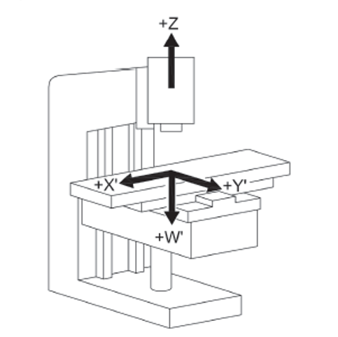
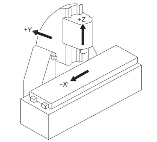
a) manually, without numerical control, operated boring and milling machines (see 3.2.1, Group 1), e.g. knee and column type milling machines (see Figures C.1 and C.2);
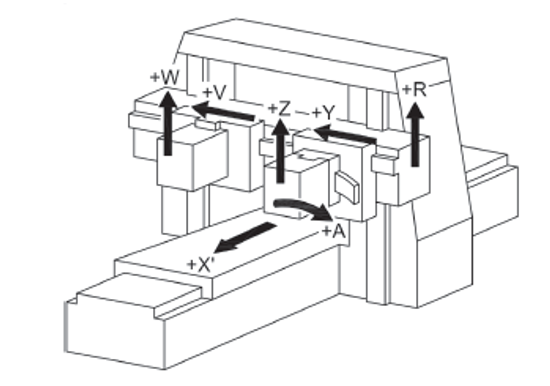
b) manually, with limited numerical control, operated boring and milling machines (see 3.2.2, Group 2), e.g. profile and contouring milling machines (see Figures C.3 and C.4);
c) numerically controlled milling machines and machining centres (see 3.2.3, Group 3), e.g. automatic milling machines and milling centres, e.g. multi-spindle milling machines, gear-milling machines (see Figures C.5 to C.7);
d) transfer and special-purpose machines (see 3.2.4, Group 4), which are designed to process only pre-specified workpieces or limited range of similar workpieces by means of a predetermined sequence of machining operations and process parameters (see Figures C.8 to C.13).
e) machines fitted with the following devices/facilities, whose hazards have been dealt with:
- tool magazine(s);
- tool changer(s);
- workpiece handling mechanism(s);
- powered workpiece clamping mechanism(s);
- swarf/chip conveyor(s);
- power-operated door(s);
- moveable operator cabin(s);
- additional equipment for turning;
- additional equipment for grinding.
This document deals with all significant hazards, hazardous situations and events relevant to this type of machinery which can occur during transportation, assembly and installation, setting, operation, cleaning and maintenance, troubleshooting, dismantling or disabling according to ISO 12100, when the machinery is used as intended and under conditions of misuse which are reasonably foreseeable by the manufacturer (see Clause 4).
This document presumes accessibility to the machine from all directions and specifies access conditions to operator positions. It also applies to workpiece transfer devices including transport devices for loading/unloading when they form an integral part of the machine.
[...]
3.2 Groups of machines
With regard to the applications and the relevant hazards, machines are subdivided into four different groups.
3.2.1 Group 1 machine: Manually controlled boring and milling machine without numerical control
machine where axis motion is controlled by actuation of a mechanical handwheel or where powered single-axis motion is controlled by mechanical, electrical or other means but without the capability for programmed multiple axes movement
Note 1 to entry: For an illustration, see Figures C.1 and C.2.
3.2.2 Group 2 machine: Manually controlled boring and milling machine with limited numerical controlled capability
machine that can be operated like a Group 1 machine by the use of mechanical or electronic handwheelsor as a machine with limited NC capabilities which are not capable of automatic program start, automatic initiated tool change, unlimited rapid axis movement and automatic workpiece change or bar feed system
Note 1 to entry: For an illustration, see Figures C.3 and C.4.
Note 2 to entry: This group of machines can be equipped with some or all of the features of Group 1 machines (manual machines without NC) and a limited numeric control system (NC) that enables the machine to provide:
- a constant surface speed (CSS);
- an axis interpolation (i.e. copying/predefined profiling);
- thread cutting cycles.
3.2.3 Group 3 machine: Numerically controlled boring-, milling machine and machining centre
numerically controlled machine capable of performing programmed multiple axis movements
Note 1 to entry: For an illustration, see Figures C.5, C.6, and C.7.
Note 2 to entry: Such machines may incorporate facilities for manual control in varying degrees.
Note 3 to entry: Machining centres can accommodate different machining processes, e.g. turning, grinding, etc.
3.2.4 Group 4 machine: Numerical controlled transfer and special purpose machine
numerically controlled machine capable to process only pre-specified workpieces or family of workpieces by means of a pre-determined sequence of machining operations
Note 1 to entry: For illustration, see Annex C, Figures C.8 to C.13 and Figures D.7 to D.8.
[...]
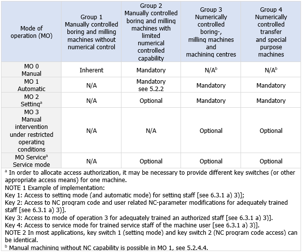
5.2.4 Mode of operation (MO)
Table 2 assigns the various, in this document standardised, modes of operation (MO) to the machine groups defined in this document (Group 1 to Group 4 machines). Standardized modes of operation may be:
- inherent: the MO is, due to technical limitations or lack of automatic control capability, the only possible mode of operation;
- mandatory: the MO shall be provided;
- optional: the MO may be provided; or
- not allowed: the MO shall not be provided to operate a machine belonging to a particular group.
Table 2 - Overview of machine groups and modes of operation
If a machine provides more than one mode of operation, the machine shall be equipped with a MO selection system.
The selected MO shall be displayed on the machine according to 6.2.2.
[...]
Annex C
(informative)
Illustrative figures as examples of machines
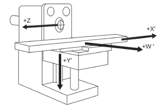
C.1 Group 1 machines
See Figures C.1 and C.2.
Figure C.1 - Example of a horizontal knee-type milling machine
Figure C.2 - Example of a vertical knee-type machine
C.2 Group 2 machines
See Figures C.3 and C.4.
Figure C.3 - Example of a single column bed-type milling machine with vertical spindle
Figure C.4 - Example of a double column bed-type milling machine (portal milling machine)
[...]
Annex D
(informative)
Illustrative figures as examples of guards
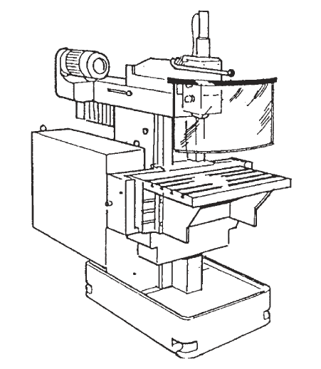
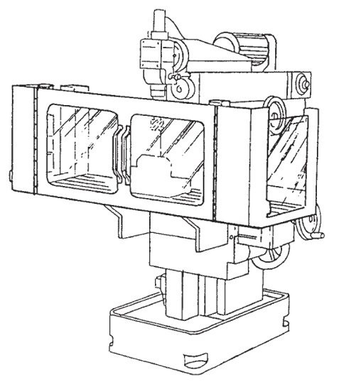
D.1 Examples of adjustable guards for milling machined.es; Group 1 (manual machines)
See Figure D.1.
c) Guard for vertical milling machine
Figure D.1 - Examples of adjustable guards for manually controlled milling machines
D.2 Examples of guards for Group 2 machines (machines with limited NC capability)
See Figure D.2.
[...]
b) Hinged door type guard
[...]
Figure D.2 - Examples of guards for Group 2 milling machines
[...]
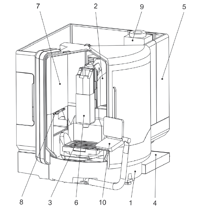
D.3 Examples of guards for Group 3 machines (automatic machines)
See Figure D.3 to D.6.
a) Guard open
[...]
Key
1 machine column (Y axis)
2 Y slide X slide (X axis)
3 slewing rotary table (SRT)/rigid table
4 cutting fluid system
5 machine enclosure
6 spindle head with motor spindle (Z axis)
7 electrical cubicle
8 tool change
9 cooling unit
10 control panel
Figure D.3 - Examples of guards for Group 3 machines (automatic machines)
...
segue in allegato
Certifico Srl - IT | Rev. 1.0 2023
©Copia autorizzata Abbonati
Matrice Revisioni:
| Rev. | Data | Oggetto | Autore |
| 1.0 | 20.06.2023 | Aggiornamento normativo | Certifico Srl |
| 0.0 | 25.10.2022 | -- | Certifico Srl |
Collegati:
UNI EN ISO 16090-1: Sicurezza macchine utensili taglio a freddo metalli
UNI EN ISO 16090-1 Sicurezza Centri di lavoro, fresatrici, transfer - P.2 Istruzioni
Direttiva macchine 2006/42/CE
Norme armonizzate Direttiva macchine 2006/42/CE (DM)
D.Lgs. 81/2008 Testo Unico salute e sicurezza lavoro
https://tussl.it/


